Welcome,
The purpose of this project was to design, build and demonstrate the correct functioning of a traffic light cruise where cars, bicycles and pedestrians could interact without any troublesome, which meant no accidents or confusions for users
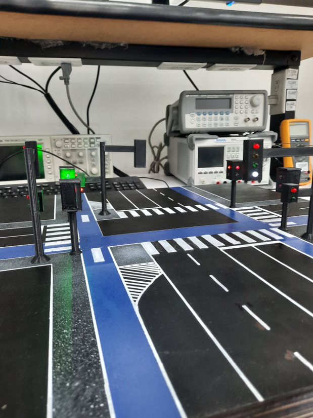
This cruise includes traffic lights for cars, bikes and pedestrians. The planted problem was simple, but the solution required a lot of analysis and understanding of the relation between the cars, bikes and pedestrians, so that there would be a good flow in the intersection and no accidents.
The objectives of the design were to control the lights and make a regressive counter for the pedestrians so that they would notice how much time left they have as they cross the street.
maqueta.final.mp4
As you saw from the videos and title, this code is for the control panel of the Traffic Lights of an intersection. This page will tell you what we did to create it as well as the model.
The Intersection
The intersection the code is for is very specific. This specific intersection is of a one-way street with a bike lane, and a two-way, double line street with bike lanes on each side. The crosswalks also have traffic lights for pedestrians. The one-way street has a turn to the right. The two-way street only has turns towards the direction of the one-way street. The bike lanes also have traffic lights, but no turns.
This is the image we based the model on, though with some changes.
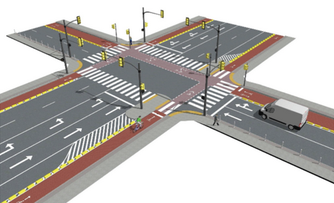
With the parts of the intersection, we derived the logic of each set of green, yellow and red lights, as well as the turn lights, and crosswalk lights. For example, when the one-way street has a green light (both straight ahead and the right turn always turn green at the same time) all the other lights turn red, except for the crosswalk to the left of that street, as they can’t turn to that direction.
The Code
The code was first made and tested in EDA Playground, though thanks to the limitations of a free and online programming software there were various errors and kinks that only appeared when we tried to upload it to the FPGA card.
The purpose of the clock divider is to change the rate at which the traffic light changes without having to change a lot of code, so you can test in the FPGA with a realistic time or with a shorter time to clearly see the changes.
An extra element we added to the code was a simple counter that lit up the LED segments of the FPGA, to observe the rate at which the traffic lights would change easier.