An Arduino oscilloscope is an essential electronic test device that monitors the steady change of electrical voltage using two-dimensional graphs, displaying voltage changes over time on the vertical Y-axis. While oscilloscopes are crucial for electronics hobbyists and professionals, commercial models are often prohibitively expensive for students and DIY enthusiasts.
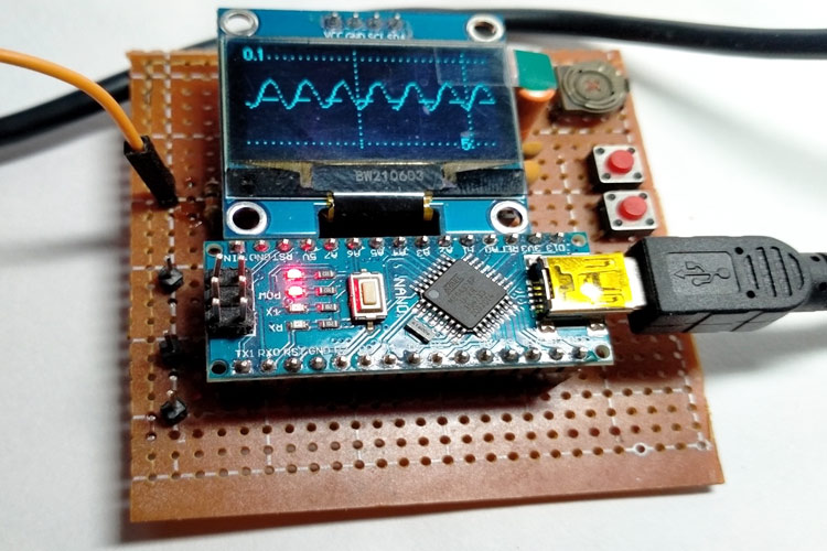
This project demonstrates how to build a simple, low-cost Arduino-based oscilloscope with a 1.3" OLED display that can visualise waveforms accurately. The project is inspired by Peter Balch's "Oscilloscope in a Matchbox" project, with modified code and hardware to suit modern requirements.
- Portable Design: Compact mini oscilloscope powered via USB
- OLED Display: 1.3" OLED display for clear waveform visualisation
- Multiple Voltage Ranges:
- DC 5V mode
- AC 500mV mode
- AC 100mV mode
- AC 20mV mode
- Voltmeter mode
- Adjustable Time Base: Multiple sweep speeds (1mS to 100mS)
- Trigger Modes: Rising and falling edge triggering
- Test Signal Generator: Built-in test signal output
- Button Controls: Two tactile switches for parameter adjustment
| Qty | Value | Device | Package | Parts | Description |
|---|---|---|---|---|---|
| 2 | - | Tactile Switch | TH | S1, S2 | Tactile switch / Buttons |
| 1 | - | Arduino Nano | ARDUINO_NANO | ARDUINO_NANO1 | Arduino Nano Board |
| 4 | 0.1uF / 16V | Capacitor | TH | C1, C2, C3, C4 | 0.1uF/16V/Ceramic Disc |
| 1 | 100K | Resistor | TH | R2 | 100K/1/4W/TH |
| 1 | 10K | Resistor | TH | R7 | 10K/1/4W/TH |
| 1 | 1K | Resistor | TH | R3 | 1K/1/4W/TH |
| 2 | 1M | Resistor | TH | R6, R8 | 1M/1/4W/TH |
| 2 | 270K | Resistor | TH | R4, R5 | 270K/1/4W/TH |
| 3 | 4.7K | Resistor | TH | R1, R9, R10 | 4.7K/1/4W/TH |
| 1 | LM358 | Op-AMP | DIL08 | IC1 | LM358 Dual Op-Amp |
| 2 | PIN1-2 | Pin Header | TH | Display / Input | 4Pin / M/F |
| 1 | - | OLED Display | I2C | - | 1.3" OLED (SH1106) |
The circuit design is straightforward and requires only a few components:
-
Operational Amplifier Stage:
- Uses LM358 dual op-amp IC
- Both op-amps are configured for AC coupling
- Gain setting of x5 with negative feedback
- Reference voltage for signal offset (adjustable via 100K potentiometer)
-
OLED Display Connection:
- Connected via I2C interface
- SCL pin: A5 (Arduino Nano)
- SDA pin: A4 (Arduino Nano)
- Pull-up resistors: 4.7K ohms
-
Input Signal Processing:
- AC input signals are processed through the op-amp stage
- Offset adjustment allows proper signal centering
- Multiple voltage ranges supported
-
Control Interface:
- Two tactile switches for parameter adjustment
- Button 1 (Pin 4): Horizontal/Time base adjustment
- Button 2 (Pin 7): Vertical/Gain and mode selection
-
Power Supply:
- USB powered (5V)
- Simple and portable design
- Wire.h - I2C communication (built-in)
- SimpleSH1106.h - Fast OLED library for SH1106 chipset (custom library by Peter Balch)
- limits.h - Standard C library (built-in)
- math.h - Mathematical functions (built-in)
enum Tmode {DC5V, AC500mV, AC100mV, AC20mV, mLogic, mVoltmeter, maxMode1};Supports different voltage ranges and measurement modes.
The analog-to-digital converter is configured with:
- Proper voltage reference selection
- Left-adjusted results for 8-bit operation
- Appropriate prescaler settings
- 128-sample buffer for waveform storage
- Real-time drawing on OLED display
- Grid and graticule overlay
- Automatic triggering system
- Long press: Opens main menu
- Short press: Cycles through settings
- Debouncing implemented in software
- Rising edge and falling edge detection
- Free-run mode for continuous display
- Hysteresis for stable triggering
- Solder all components on perfboard according to the circuit diagram
- Connect the OLED display via I2C (A4/SDA and A5/SCL)
- Install tactile switches on pins 4 and 7
- Verify all connections
- Download and install Arduino IDE
- Install the SimpleSH1106 library (available in project files)
- Connect Arduino Nano to your computer via USB
- Open the oscilloscope sketch in Arduino IDE
- Select Tools → Board → Arduino Nano
- Select the correct COM port
- Upload the code
- Power the oscilloscope via USB
- Use the test signal output (Pin 3) to verify operation
- Adjust time base and gain using the buttons
- Connect external signals to the input
Access the main menu by holding either button for 1 second:
Menu Options:
- Time Base: 1mS, 2mS, 5mS, 10mS, 20mS, 50mS, 100mS
- Gain/Mode: 5V DC, 0.5V AC, 0.1V AC, 20mV AC, Voltmeter
- Trigger: Rising or Falling edge
- Test Signal: Various frequencies (31Hz to 31250Hz) or Off
- Vcc Display: Shows supply voltage
Horizontal Button (Pin 4):
- Short press: Change time base
- Long press: Enter menu
Vertical Button (Pin 7):
- Short press: Change voltage range/mode
- Long press: Enter menu
The oscilloscope displays:
- Waveform trace: Real-time signal visualization
- Grid lines: Vertical and horizontal references
- Scale labels: Voltage and time scales
- Trigger indicator: Shows trigger point
The oscilloscope includes a test signal generator that can output:
- Square waves at various frequencies
- Useful for testing and calibration
- Available on Pin 3
- Enable test signal in menu
- Connect Pin 3 to input
- Adjust time base to view complete waveforms
- Verify trigger functionality
The oscilloscope can display various waveform types:
- Sine waves: Smooth periodic signals
- Square waves: Digital signals and PWM
- Triangle waves: Ramp signals
- Complex waveforms: Audio and modulated signals
| Parameter | Specification |
|---|---|
| Display | 1.3" OLED (128x64 pixels) |
| Input Channels | 1 (single channel) |
| Voltage Ranges | 20mV/div to 5V/div |
| Time Base | 0.1mS/div to 20mS/div |
| Input Impedance | ~1MΩ |
| Sampling Rate | Up to 1 Msps |
| Buffer Size | 128 samples |
| Power Supply | 5V USB |
| Trigger | Rising/Falling edge |
1. No Display Output
- Check I2C connections (A4, A5)
- Verify OLED power supply
- Check SimpleSH1106 library installation
2. Incorrect Waveform Display
- Adjust trigger level
- Check input signal amplitude
- Verify ground connections
3. Erratic Behavior
- Check power supply stability
- Verify button connections
- Update code if using modified version
4. Compilation Errors
- Ensure SimpleSH1106.h library is installed
- Check Arduino IDE board selection
- Verify all library dependencies
- Add BNC Connector: Professional input connector for better signal integrity
- Battery Power: Add rechargeable battery for portable operation
- Dual Channel: Expand to two-channel operation
- Higher Sampling Rate: Optimize code for faster sampling
- FFT Analysis: Add frequency spectrum display
- Data Logging: Store waveforms to SD card
- USB Communication: Send data to PC for analysis
- Original Article: DIY Mini Oscilloscope using Arduino Nano
- Inspiration: Peter Balch's "Oscilloscope in a Matchbox"
- Related Projects:
-
Global Variables & Constants
- Mode settings, buffer arrays, display parameters
-
Image Data
- Menu graphics stored in PROGMEM
- Waveform icons and UI elements
-
Display Functions
drawScreen(): Renders waveform and graticuledrawBox(): Creates menu bordersdrawMainMenu(): Main menu interface
-
ADC Functions
initADC(): Configures ADC registersGetADCSamples(): Captures waveform dataSendADC(): Processes and displays samples
-
Control Functions
setSweep(): Adjusts time basesetMode(): Changes voltage rangeCheckButtons(): Handles user input
-
Utility Functions
readVcc(): Measures supply voltagemyDelay(): Non-blocking delay- Timer and interrupt handlers
- Maximum Input Voltage: Do not exceed 5V DC input
- AC Signals: Limited to specified ranges (500mV, 100mV, 20mV AC)
- No High Voltage: This is NOT suitable for mains voltage measurements
- ESD Protection: Use anti-static precautions when handling components
- Power Supply: Use regulated 5V USB power only
This project is based on Peter Balch's work and is subject to the GNU General Public License.
Feel free to contribute improvements, bug fixes, or additional features. Submit your ideas and modifications through the Circuit Digest forums.
- Peter Balch: Original "Oscilloscope in a Matchbox" project creator
- Circuit Digest: Project documentation and testing
- Arduino Community: Libraries and support
For questions, suggestions, or troubleshooting help:
- Visit the Circuit Digest Forum
- Check the original article for detailed explanations
- Join the Arduino community for general Arduino support
Built with ❤️ by the DIY Electronics Community
Last Updated: 2024