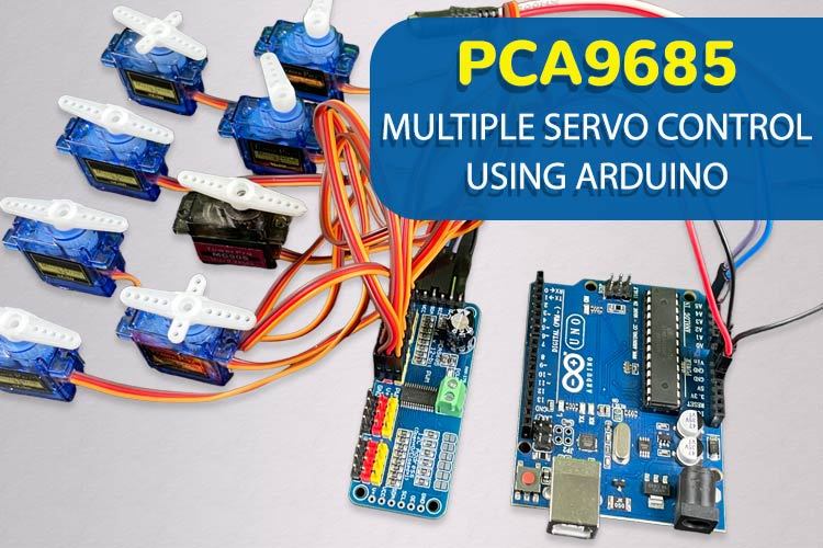
This project demonstrates how to control multiple servo motors simultaneously using the PCA9685 16-channel PWM/Servo Driver module with Arduino. The PCA9685 module solves the limitation of Arduino's 6 PWM pins by providing 16 independent PWM outputs through I2C communication.
Original Tutorial: PCA9685 Multiple Servo Control Using Arduino
- Control up to 16 servo motors with a single PCA9685 module
- I2C communication using only 2 Arduino pins (SDA & SCL)
- Cascadable up to 62 modules (992 total outputs)
- Built-in clock eliminates continuous signal transmission
- 3.3V and 5V compatible
- Precise 12-bit PWM resolution
| Component | Quantity | Description |
|---|---|---|
| Arduino Uno R3 | 1 | Main microcontroller |
| SG90 Servo Motor | 8 | Standard servo motors |
| PCA9685 16-Channel Module | 1 | PWM/Servo driver |
| External 5V Adapter | 1 | Power supply for servos |
| Jumper Wires | As needed | Connections |
- VCC: Power supply (3.3V to 5V) for module circuitry
- GND: Ground connection
- SDA: I2C data line (connect to Arduino A4)
- SCL: I2C clock line (connect to Arduino A5)
- OE: Output Enable (optional, pull low to disable outputs)
- V+: External power for servos (connect to 5V adapter)
Arduino    PCA9685
VCC    ->  5V
GND    ->  GND
A4     ->  SDA
A5     ->  SCL
- Connect Arduino VCC and GND to PCA9685 VCC and GND
- Connect Arduino A4 to PCA9685 SDA
- Connect Arduino A5 to PCA9685 SCL
- Connect external 5V adapter positive to PCA9685 V+
- Connect external adapter ground to common ground
- Connect servos to channels 0-7 on PCA9685
- Open Arduino IDE
- Go to Tools > Manage Libraries
- Search for "Adafruit PWM Servo Driver"
- Install the library
#include <Adafruit_PWMServoDriver.h>
Adafruit_PWMServoDriver board1 = Adafruit_PWMServoDriver(0x40);
#define SERVOMIN 125 // Minimum pulse length (0 degrees)
#define SERVOMAX 625 // Maximum pulse length (180 degrees)
void setup() {
Serial.begin(9600);
Serial.println("16 channel Servo test!");
board1.begin();
board1.setPWMFreq(60); // Servos operate at ~60 Hz
}
void loop() {
// Set all servos to 0 degrees
for(int i=0; i<8; i++) {
board1.setPWM(i, 0, angleToPulse(0));
}
delay(1000);
// Sweep all servos from 0 to 180 degrees
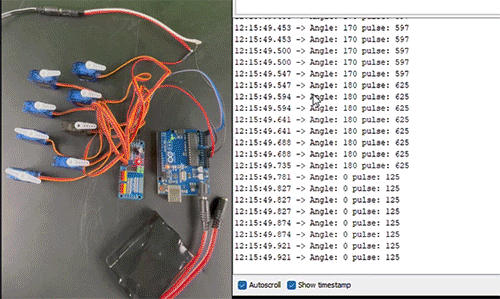
for(int angle = 0; angle < 181; angle += 10) {
for(int i=0; i<8; i++) {
board1.setPWM(i, 0, angleToPulse(angle));
}
delay(100);
}
}
int angleToPulse(int ang) {
int pulse = map(ang, 0, 180, SERVOMIN, SERVOMAX);
Serial.print("Angle: "); Serial.print(ang);
Serial.print(" pulse: "); Serial.println(pulse);
return pulse;
}- setPWM(channel, on, off): Sets PWM values for specific channel
- setPWMFreq(frequency): Sets PWM frequency (60Hz for servos)
- angleToPulse(angle): Converts angle to pulse width
You can cascade multiple PCA9685 modules by:
- Setting unique I2C addresses using address jumpers (A0-A5)
- Creating separate objects for each module
- Default address is 0x40, next would be 0x41, etc.
Adafruit_PWMServoDriver board1 = Adafruit_PWMServoDriver(0x40);
Adafruit_PWMServoDriver board2 = Adafruit_PWMServoDriver(0x41);- Board 0: Address = 0x40 (no jumpers)
- Board 1: Address = 0x41 (bridge A0)
- Board 2: Address = 0x42 (bridge A1)
- Board 3: Address = 0x43 (bridge A0 & A1)
- PWM Resolution: 12-bit (4096 steps)
- I2C Address: 0x40 (default, configurable)
- Max Current per Pin: 25mA
- Operating Voltage: 3.3V to 5V
- PWM Frequency: Configurable (60Hz for servos)
- Output Resistance: 220Ω series resistor per pin
- Servos not moving: Check external power supply connection
- Erratic movement: Ensure proper ground connections
- Communication errors: Verify I2C connections (SDA/SCL)
- Power issues: Use adequate external power supply (not Arduino 5V)
- Arduino cannot power multiple servos directly
- PCA9685 provides control signals, not power
- All channels share the same PWM frequency
- Maximum 25mA per output pin
- Robotics: Multi-joint robot arms and legs
- Automation: Multiple actuator control systems
- Animatronics: Character movement systems
- RC Projects: Multi-servo aircraft/vehicle control
- IoT Devices: Smart home automation systems
The complete Arduino sketch is provided above. Modify the servo count in the for loops if using different numbers of servos.
- Web Control: Add ESP32/ESP8266 for web-based servo control
- Sensor Integration: Add sensors for autonomous servo positioning
- Multiple Modules: Cascade additional PCA9685 modules for more servos
- Precise Control: Implement position feedback for closed-loop control
- Original Circuit Digest Tutorial
- Adafruit PCA9685 Library Documentation
- Servo Motor Basics
- Arduino Projects
This project is based on the open-source tutorial from Circuit Digest. Please refer to their terms and conditions for usage rights.
Created by: Circuit Digest Team
Tutorial Source: https://circuitdigest.com/microcontroller-projects/pca9685-multiple-servo-control-using-arduino