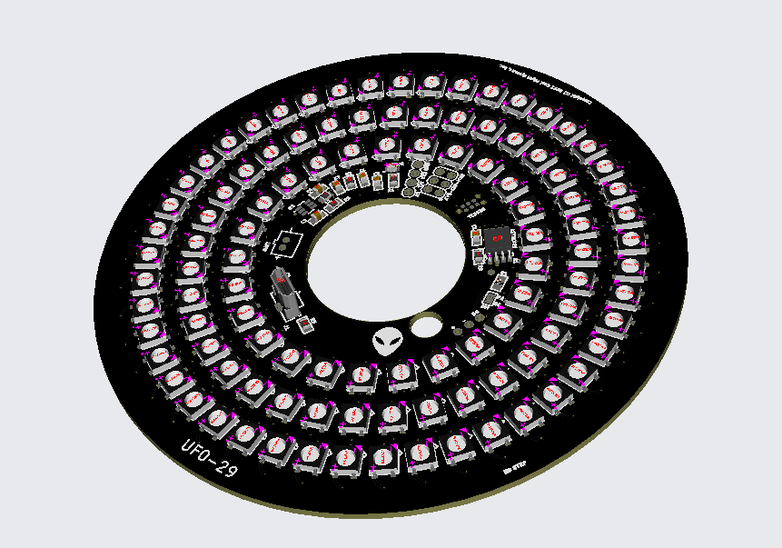
Programmable 210 NEOPIXEL LED HPR saucer/spool
- 4.54 in Diameter
- 29mm motor mount
- 105 NEOPIXEL per side, dedicated MCU per side (2 CPU's for A/B sides)
- Multiprocessor design - A/B Sides completely independent strobe/pattern
- 3.7-5V input power
- 2-Pin JST-PH for 1S LIPO battery (400mA and more recommended)
- 3A Buck/Boost onboard for 1S Lipo
- Button for top/bottom selected (opposite side of button affected)
- Arduino compatible ATTINY85 @16Mhz
- 105 LED's per side
- Modified Adafruit Neopixel library to fit maximum number of full programmable neopixels on Attiny85
- Programmable sequences
- Download and install the Arduino IDE (time of this writing it is Arduino IDE 2.0.3)
- Connect the AVR-ISP-MK2 Olimex device programmer to the target and connect USB cable to your system.
- Start the Arduino IDE
- Install Arduino AVR Boards
- Install AttinyCore to enable ATTINY85 Board support
-
AttinyCore can be installed using the boards manager. The boards manager URL is:
-
File->Preferences on a PC, or Arduino->Preferences on a Mac, enter the above URL in "Additional Boards Manager URLs
-
Tools -> Boards -> Boards Manager...
-
Select "ATTinyCore by Spence Konde" and click "Install".
-
- 5V 4A Power Supply
- JST-PH 2 Pin Adapter
- 2.1mm DC Barrel Jack Adapter for Power Supply
- AVR-ISP-MK2 Olimex
- Tagconnect TC2030-IDC-NL AVR ICSP adapter
- Follow the Software Setup instructions above
- Open the ufo29 sketch folder in the Arduino IDE, you should have the file ufo29.ino open
- Configure the Arduino IDE ATTINY85 settings for the UFO29
- Check the below settings once ATTinyCore is installed:
- Tools->Board->AttinyCore->Attiny25/45/85 (No Bootloader)
- Tools-> B.O.D. Level (Only set on bootload) -> Disabled (saves power)
- Tools->Chip -> Attiny85
- Tools->Clock Source -> 16Mhz (PLL) or 16.5Mhz PLL Tweaked (for a little more performance)
- Tools->Programmer -> AVRISP mkII
- Tools->Save EEPROM->EEPROM retained
- Tools->millis/micros -> Enabled-
- Perform the build.
- Sketch->Verify/Compile
- Next, program the Bootloader (only needs to be done once)
- Tools->Burn Bootloader
- Build and Upload
- Sketch->Upload
Once you have the bootloader programmed, you can add your own sequences and simply build/upload.
You can press the top button to change the bottom LED array and the bottom button to change the top.
NOTE: you will need to develop on one of the CPU's and then re-connect to the bottom header and program the other one.
NOTE: It is absolutely critical you burn the Bootloader before programming since this sets the eFUSE options on the MCU and therefore the clocks/IO's.
- Load the Arduino sketch in sw folder
- Build/upload sketch
- Order a 12in piece of thin-wall 29 mm fiberglass tube from Mach-1 Rocketry for the motor mount (you need 7")
- You also need a carbon fiber launch lug adapter, you can order a unidirectional carbon fiber rod for a 1/8" Estes rod here from Rockwest Composites
- For length, order 7" to 12" quantities
- The optimal length for a saucer or spool is L =1.5 D Where D is the diameter of the spool
- The Saucer Plate is - 4.54" diameter so you need a 6.8" long 29mm tube for optimal stability.
- See also Spool Rocket Center of Pressure
- Use a small battery and tape to the side of the airframe section used as motor mount
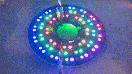
- The 400ma Adafruit LIPO is perfect to tape to the side of the motor tube and gets about 15 minutes with Pikachu strobe sequence activated
- Use the ASP-Rocketry Hang-time Mylar parachute and "dog barf" for protection. Spectacular night flying is possible with the 36" Mylar chute.